
 Gọi điện
 Nhắn tin
 Chỉ đường

Công tác đất

Xem thêm
Introduction

Prefabricated Vertical Drains (PVDs) or ‘Wick Drains' are composed of a plastic core encased by a geotextile for the purpose of expediting consolidation of slow draining soils. They are typically coupled with surcharging to expedite preconstruction soil consolidation. Surcharging means to pre-load soft soils by applying a temporary load to the ground that exerts stress of usually equivalent or greater magnitude than the anticipated design stresses. The surcharge will increase pore water pressures initially, but with time the water will drain away and the soil voids will compress. These prefabricated wick drains are used to shorten pore water travel distance, reducing the preloading time. The intent is to accelerate primary settlement. Pore water will flow laterally to the nearest drain, as opposed to vertical flow to an underlying or overlying drainage layer. The drain flow is a result from the pressures generated in the pore water. Below demonstrate vertical water flow without the use of prefabricated wick drains, and horizontal water flow with the use of wick drains.
PVD (PBD &PCD)

1. Hydraulic (medium, low depth)
2. Hydraulic type (special machine) Depth: 50m or less
3. Vibration type (medium, low depth)
4. Great depth type (leader length: 67m, depth: 63m)
Plastic Board Drain, Plastic Cylindrical Drain Method
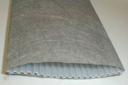
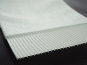
PVDs have a channeled or studded plastic core wrapped with a geotextile. The plastic core functions as support for the filter fabric, and provides longitudinal flow paths along the drain length. It also provides resistance to longitudinal stretching as well as buckling of the drain. The drain jacket acts as a filter to limit the passage of fine grained soil into the core area. It also functions to prevent closure of the internal water flow paths under lateral soil pressure.
Layfield Wick Drain Example
Geosupply Wick Drain Example
Light-weight drains have a width to thickness ratio of 30-35. It is desirable for the surface area, which will permit seepage into the drain, to be 0.2-0.3 in2 (150-200 mm2) per 0.4 in (1 mm) length. The wick drains should be installed with a center to center spacing of 3 to 8 ft [17]. This will be discussed more in the design parameters section.
PVD Installation
PVDs are installed by a hollow steel mandrel encasing the wick drain material. The mandrel is driven into the ground by a stitcher attached to an excavator carrier, as seen in figure I. This is a vibrating force, but static options are also available for areas near underground utilities. At the base of the mandrel, the wick is looped through a steel anchor to secure the drain in place. Once the desired depth is reached, the drain is anchored and the mandrel is extracted. The mandrel is withdrawn 15 to 20 cm above the surface for the wick drain to be cut. If the soil the mandrel is driving into is exceedingly stiff, and the mandrel cannot be vibrated or hammered into the ground, predrilling may become necessary.
Depth of Installation
Drains are not likely to accelerate consolidation if induced effective stress is not greater than the preconsolidation stress. The optimum depth of the wick drains lies within the preconsolidation stress margin as the stress from the surcharge diminishes with depth. However, if there is a pervious soil layer below the preconsolidation margin, the wick drain should be extended into that soil layer. This will aid in assuring the discharge of the water.
Width of Installation
Soil strata are not defined as entirely uniform layers, therefore there may not be equal volumes of water to be drained. If some portions of a layer have a greater amount of drainage, the soil will settle to fill those voids. This leads to differential settlements and could prolong the consolidation time. To help avoid this issue, wick drains should be distributed across the entire footprint of an embankment and a small distance beyond. It is advised to place the outermost rows of drains between one third and one half of the proposed embankment's height beyond the embannkment. However when designing the wick drain’s layout, homogeneous soil can be assumed for simplicity.
PVD Work Flowchart


1. Installation location indication
- Measure the construction point and display the position
2. Fixing the equipment in place
- Keep the mandrel vertical after fixing the PVD equipment in place
3. Attaching anchor plate
- Mounting anchor plate on drain board


4. Intrusion of casing
- Intrusion of the casing into the installation position
5. Casing pull
- Casing Drawing and Drain Board Cutting
6. Completion and movement
- Drain Board clearance in the drainage layer
PVD / PBD Video


